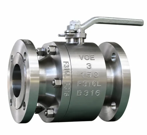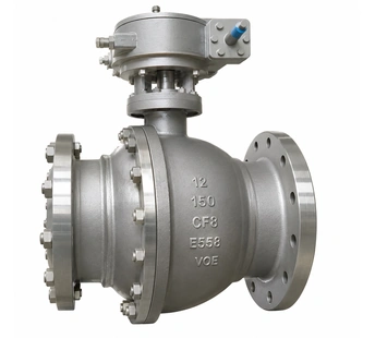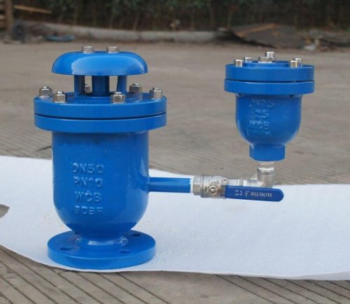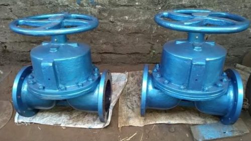


Three-way ball valves are valves with three connections instead of the usual two. They are used where a process line needs to send flow to a different line, split it between two outlets or blend two streams into one. A single three-way valve takes the place of several two-way valves and fittings, reducing pipework, installation space and the number of potential leak points.
Three-way ball valve manufacturers in Europe supply these valves through Valves Only Europe for oil and gas processing, chemical plants, water treatment, power generation, tank and process-line switching duties.
| Operation | Function | Design |
| Quarter-Turn | Flow Diversion, Mixing and Routing | L-Port / T-Port Floating Ball |
Design & Working Principle
The body has three ports, usually arranged at right angles to each other, and the ball inside has an L-shaped or T-shaped bore. Seats around the ports seal against the ball, which is held in place by the seats as in a floating ball valve, and the stem turns the ball between its flow positions. In an L-port valve the bore connects two ports at a time. A T-port bore can connect all three ports together or connect selected pairs, depending on the ball position.
Rotating the ball changes which ports are connected. In an L-port valve, a quarter-turn switches the flow from one outlet to the other. In a T-port valve, the ball can be set to divert flow to either outlet, to connect all three ports for mixing or distribution, or to block one port, depending on the port arrangement. The valve moves in quarter-turn steps between defined flow positions, operated by hand or by an electric or pneumatic actuator in response to a control signal. The flow diagram should be matched to the process requirement.
Key Product Features
✓ Three-port design for diverting, mixing or routing flow
✓ L-port and T-port ball configurations
✓ Floating ball construction
✓ Selectable flow paths for diversion or mixing
✓ Compact alternative to several separate valves
✓ Quarter-turn operation between flow positions
✓ Manual, electric and pneumatic operation
✓ Flanged, screwed, threaded and butt-weld end connections
Technical Specifications
| Parameter | Specification |
| Product Type | Three Way Ball Valve |
| Size Range | DN15–DN200 |
| Pressure Rating | ASME Class 150–300 (PN16–PN63) |
| Standards | API 6D; ISO 17292; ASME B16.34; API 598 |
| Body Material | Carbon steel and stainless steel (CF8M) |
| Casting Grades | ASTM A216 WCB; ASTM A351 CF8/CF8M/CF3M |
| Forged Grades | ASTM A105; ASTM A182 F304/F316 |
| Seat Material | PTFE, RPTFE, PFA or FEP |
| Bore Design | L-port or T-port flow passage |
| End Connections | Flanged, screwed, threaded or butt-weld |
| Operation | Lever, pneumatic actuator or electric actuator |
| Flow Function | Flow diversion, mixing and routing, depending on L-port or T-port design |
Industries and Applications
- Oil & Gas Pipelines
- Chemical & Petrochemical Processing
- Water Treatment Systems
- Industrial Process Pipelines
- Power Generation
- Mining & Mineral Processing
- Marine & Offshore Systems
- Industrial Utility Systems