
Suction Diffuser Manufacturer in Europe
A suction diffuser is installed at the inlet of a centrifugal pump to improve incoming flow conditions while providing debris protection and a compact change in flow direction. The unit combines the functions normally provided by a suction elbow, reducer, strainer and flow-straightening section into a single body.
Conditioning Flow at Pump Suction Inlets
- Centrifugal pumps perform best when the fluid approaching the impeller eye has a reasonably uniform velocity distribution.
- Elbows, reducers and other fittings located close to the pump inlet can create Swirl, Uneven velocity distribution, Turbulence, Local flow separation.
- These conditions can affect pump performance and may contribute to vibration, noise or uneven hydraulic loading.
- A suction diffuser uses internal flow-straightening elements to reduce rotational and distorted flow before the fluid enters the pump suction nozzle.
- The diffuser does not replace correct pump system design, and adequate NPSH and suitable piping arrangements must still be maintained.
Elbow, Strainer and Flow Straightening Functions
A suction diffuser normally performs several functions within one compact component.
- Elbow Function: Changes flow direction, typically by 90°, toward the pump inlet.
- Reducer Function: Connects a larger suction line to a smaller pump inlet without a separate reducer.
- Strainer Function: Removable basket captures rust, welding slag, debris and larger particles before they reach the pump.
- Flow Straightening Function: Internal vanes reduce swirl and create a more uniform flow into the pump.
Internal Screen and Straightening Vane Design
The internal strainer commonly consists of perforated stainless-steel sheet and may incorporate a finer mesh where additional debris retention is required.
During system commissioning, a coarser or temporary screen may be used to collect construction debris. The operating screen can then be installed after the pipeline has been flushed.
Straightening vanes are positioned downstream of the strainer to reduce:
- Swirl
- Cross flow
- Large scale turbulence
The screen and vane assembly should be securely supported to prevent deformation under differential pressure. The design should also allow removal of the strainer element without dismantling the pump or connected pipeline.
Technical Specifications
| Parameter | Typical Specification |
| Size Range | DN50–DN600 |
| Pressure Rating | PN16–PN25 / ASME Class 150–300 depending on design |
| Body Materials | Cast Iron, Ductile Iron, Fabricated Carbon Steel, Stainless Steel |
| Strainer Material | Perforated Stainless Steel; optional mesh lining |
| Flow Conditioning | Internal straightening vanes |
| End Connections | Flanged; grooved/threaded configurations where specifically designed |
| Flange Standards | EN 1092-1 / EN 1092-2 or ASME B16.5 according to material/design |
| Temperature Range | Approximately -20°C to +150°C depending on body and sealing materials |
| Support | Adjustable support foot where provided |
| Accessories | Gauge tapping, Drain Connection, optional magnetic insert |
| Testing | Hydrostatic shell testing according to applicable product/project requirements |
| Installation | Pump suction inlet |
Screen Free Area and Pressure Drop
The strainer must provide sufficient free flow area to capture debris without creating excessive suction loss.
Important parameters include:
- Pump design flow rate
- Strainer perforation size
- Mesh size
- Effective screen area
- Fluid viscosity
- Solids concentration
- Clean-screen pressure drop
- Dirty-screen pressure drop
As debris accumulates, the differential pressure through the screen increases.
The suction diffuser should therefore be sized using the pump’s operating flow and available NPSH rather than simply matching the nominal suction-pipe diameter.
Drain, Gauge and Cleaning Connections
Suction diffusers can include auxiliary connections that simplify commissioning and maintenance.
Gauge Connection
A pressure-gauge tapping can be used to monitor suction pressure near the pump inlet.
Drain Connection
A drain connection allows trapped liquid and debris to be removed when the unit is isolated for maintenance.
Strainer Access
A removable cover provides access to the internal basket for inspection and cleaning.
Where provided, an optional magnetic insert can help collect ferrous particles during commissioning or operation.
Pump Inlet Sizing and Installation
The diffuser should be selected according to the required pump flow rate and pump-suction connection.
Important installation considerations include:
- Pump manufacturer’s inlet requirements
- Design and maximum flow
- Available NPSH
- Allowable pressure loss
- Correct inlet/outlet orientation
- Adequate upstream pipe arrangement
- Support of the diffuser body
- Access for screen removal
Where an adjustable support foot is provided, it should carry the weight of the diffuser rather than allowing that load to be transferred to the pump nozzle. Pipeline misalignment should not be corrected by pulling the diffuser into position with flange bolts.
Water and Process Pump Applications
Suction diffusers are commonly installed on centrifugal pump systems in:
- Chilled-water circuits
- Cooling-water systems
- Water treatment plants
- Booster pump stations
- District energy networks
- Power generation auxiliaries
- Fire water systems
- Industrial process water systems
- Marine cooling systems
- General circulation pump installations
Their compact construction is particularly useful where there is limited space for a separate elbow, reducer, strainer and long straight suction pipe section.
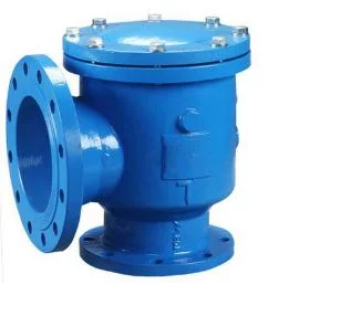
Suction Diffuser
Price range: €68.00 through €6,088.00