
Foot Valve Manufacturer in Germany
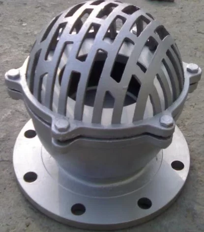
A foot valve is a non-return valve installed at the inlet of a pump suction line to retain the liquid column when the pump stops. The valve combines a check-valve mechanism with an inlet strainer so fluid can enter the suction pipe while reverse flow is restricted and larger debris is prevented from reaching the pump.
Maintaining Prime in Pump Suction Lines
Surface-mounted centrifugal pumps commonly require the suction line and pump casing to remain filled with liquid before start-up.
Without a non-return device, the liquid column can drain back toward the source when the pump stops.
A foot valve helps retain this column.
During pump operation:
- Pump suction creates a pressure difference across the valve.
- The disc, flap or other closure element opens.
- Fluid enters through the strainer.
- Flow passes upward through the suction pipe toward the pump.
When the pump stops:
- Forward velocity decreases.
- Reverse flow begins to act against the closure element.
- The disc returns to the seat.
- The liquid column is retained inside the suction line.
This reduces the need for repeated manual priming during subsequent pump starts.
Integrated Non Return and Straining Functions
A foot valve performs two separate functions in one assembly.
Non-Return Function
The internal disc or flap permits flow toward the pump and closes against reverse flow.
Depending on design, closure can be assisted by:
- Gravity
- Reverse pressure
- Spring force
Straining Function
An inlet screen prevents larger debris from entering the valve and suction pipe.
The strainer can help protect:
- Pump impellers
- Mechanical seals
- Internal pump passages
- Downstream equipment
The foot valve should not be treated as a fine filtration device. Its screen should retain damaging debris while maintaining adequate suction flow.
Disc, Strainer and Seat Construction
Foot valve designs can use:
Swing or Flap Disc
A hinged closure element moves away from the seat under forward flow and returns when the pump stops.
Spring-Assisted Disc
A spring can accelerate closing and help maintain consistent seating where the design requires it.
Seat
Seating arrangements can include:
- Metal seat
- EPDM
- NBR
- FKM
- Other water-compatible resilient materials
Strainer
The inlet screen can be:
- Perforated
- Slotted
- Mesh-supported where appropriate
Stainless-steel screens can be used where improved corrosion resistance is required.
The strainer should be removable or accessible for cleaning wherever possible.
Technical Specifications
| Parameter | Typical Specification |
| Size Range | DN25–DN600 |
| Pressure Rating | PN10, PN16; higher ratings design-dependent |
| Body Materials | Cast Iron, Ductile Iron, Stainless Steel, Bronze |
| Closure | Swing Disc, Flap or Spring-Assisted Disc depending on design |
| Seat / Seals | EPDM, NBR, FKM or metal seating according to application |
| Strainer | Perforated or Slotted Screen |
| Strainer Material | Stainless Steel or body-compatible material |
| End Connections | Flanged, BSP/NPT Threaded, Threaded Union depending on size |
| Flanges | EN/DIN drilling according to selected PN rating |
| Operation | Automatic / Self-Actuated |
| Flow Direction | From source toward pump |
| Testing | Hydrostatic shell and seat testing according to applicable product/project requirements |
| Application | Pump Suction / Water Intake |
Suction Lift and Head Loss Considerations
A foot valve adds hydraulic resistance to the suction side of the pump.
This resistance is important because excessive suction pressure loss can reduce the available margin against pump cavitation.
Pressure loss is influenced by:
- Flow rate
- Valve size
- Disc opening
- Strainer free area
- Screen blockage
- Fluid viscosity
- Suction-pipe length
- Number of fittings
- Suction lift
The foot valve should therefore be sized according to pump flow and allowable suction loss, not simply by matching the smallest available valve to the pipe connection.
A larger suction valve may sometimes be preferred where it reduces inlet velocity and pressure loss.
The complete suction arrangement should maintain adequate Net Positive Suction Head Available (NPSHA) for the selected pump.
Strainer Open Area and Solids Handling
The strainer should provide sufficient open area to prevent excessive flow restriction.
If the screen opening is too small or the effective free area is inadequate:
- Suction pressure loss increases
- Pump capacity can decrease
- Cavitation risk can increase
- Cleaning frequency increases
If the openings are too large, damaging debris may pass into the pump.
Selection should therefore consider:
- Maximum expected particle size
- Solids concentration
- Pump passage size
- Required debris retention
- Clean screen pressure loss
- Dirty screen pressure loss
- Maintenance interval
The screen area should provide a comfortable flow margin even as limited debris accumulates.
Foot valves used in heavily contaminated or sludge-laden media require special consideration because solids can prevent the closure element from fully seating.
Pump Intake Applications
Foot valves are used in:
- Municipal water pumping
- Irrigation systems
- Industrial process-water intake
- Reservoir suction lines
- Open-well pumping
- Construction dewatering
- Firewater storage systems
- Cooling-water intake
- Marine water intake
- General surface-pump suction systems
For clean water, a standard resilient- or metal-seated construction can be used according to pressure and material requirements.
Foot Valve
Price range: €21.81 through €707.90