
Diaphragm Valve Manufacturer in Germany
Diaphragm valves isolate or regulate fluid by moving a flexible diaphragm toward or away from the valve body’s sealing surface. The diaphragm separates the operating mechanism from the process medium, reducing the number of wetted moving components and making the valve suitable for corrosive, abrasive, viscous and solids containing fluids.
Fluid Isolation Using a Flexible Diaphragm
- The diaphragm is connected to a compressor or stem mechanism located above the flow passage.
- During closing, the compressor moves downward and presses the diaphragm against the body weir or sealing surface.
- During opening, the compressor retracts and allows the diaphragm to lift away from the flow path.
- Because the operating stem does not pass directly through the process boundary, conventional stem packing is not required in the same manner as many gate, globe or ball valve designs.
- The diaphragm also isolates the bonnet and actuator components from direct contact with the process medium.
This makes the design useful for fluids that are:
- Corrosive
- Abrasive
- Viscous
- Contaminated with suspended solids
provided the diaphragm and body materials are compatible.
Weir Type and Straight Through Designs
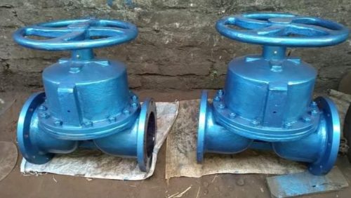
Weir-Type Diaphragm Valve
- Raised weir with short diaphragm travel
- Good throttling and reliable shut-off
- Reduced diaphragm flexing
- Used in chemical, water-treatment and process systems
Straight-Through Diaphragm Valve
- Open flow path without a raised weir
- Lower flow resistance
- Suitable for viscous, slurry and fibrous media
- Reduced solids accumulation
- Requires greater diaphragm travel
Body and Compressor Construction
Current standard configurations can use cast iron or ductile iron bodies.
Cast Iron
Suitable for moderate-pressure water, effluent and compatible general process applications.
Ductile Iron
Provides higher mechanical strength and impact resistance and is commonly used for water, wastewater and selected slurry systems.
The compressor distributes stem force across the diaphragm during closing.
Internal operating components are normally located outside the process medium, helping reduce corrosion exposure of the stem and actuator mechanism.
For corrosive applications, the body can be protected with a suitable lining or coating where required by the actual design.
Technical Specifications
| Parameter | Typical Specification |
| Nominal Size | DN15–DN300 |
| Pressure Rating | PN10, PN16, PN25 / Class 150 depending on design |
| Body Designs | Weir Type, Straight Through |
| Body Materials | Cast Iron, Ductile Iron |
| Diaphragm Materials | EPDM, NBR, FKM, PTFE-Faced |
| Lining Options | Rubber, Ebonite, PTFE/PFA where offered |
| End Connections | Flanged, Threaded; other configurations design-dependent |
| Actuation | Handwheel, Pneumatic, Electric |
| Typical Temperature | Approximately -10°C to +150°C depending primarily on diaphragm material |
| Flow Direction | Generally bidirectional, subject to specific design |
| Diaphragm Valve Standard | EN 13397 for applicable metallic diaphragm valves |
| Face to Face | EN 558 / applicable manufacturer dimensions |
| Flange Standards | EN 1092 / ASME B16.5 according to body and project requirements |
| Testing | EN 13397 / EN 12266-1 or applicable project requirements |
Manual and Automated Operation
Handwheel Operation
Manual diaphragm valves use a handwheel and threaded stem to move the compressor toward or away from the diaphragm.
This configuration is suitable where:
- Operation is infrequent
- Local control is acceptable
- Automation is not required
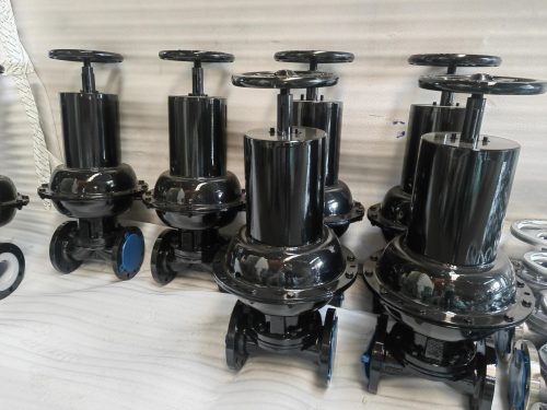
Pneumatic Actuation
A pneumatic actuator uses compressed air to move the compressor.
Pneumatic operation is suitable for:
- Frequent cycling
- Remote isolation
- Automated process control
- Fail-open or fail-closed configurations where applicable
Electric Actuation
Electric actuators provide motor-driven operation and can be integrated with PLC, DCS or local control panels.
On/off or modulating operation may be provided where the selected valve and actuator are suitable for control duty.
Actuator thrust must be matched to valve size, pressure and diaphragm closing force.
Media Compatibility and Temperature Limits
Diaphragm valve suitability is often determined more by the diaphragm and lining materials than by the metallic body.
Selection should consider:
- Chemical composition
- pH
- Solids concentration
- Fluid viscosity
- Operating temperature
- Pressure
- Abrasiveness
- Cleaning chemicals
- Frequency of operation
A body material may remain suitable at a temperature where the diaphragm is already above its practical operating limit.
Likewise, a PTFE-faced diaphragm can provide strong chemical resistance but may have different pressure and flex life characteristics than an elastomeric diaphragm.
Pressure temperature limits should therefore be based on the complete valve construction.
Corrosive and Abrasive Fluid Applications
Diaphragm valves are used in systems where keeping the operating mechanism separated from the process fluid provides an advantage.
Typical applications include:
- Water treatment
- Wastewater and effluent
- Chemical dosing
- Corrosive chemical transfer
- Mining and mineral processing
- Slurry pipelines
- Pulp and paper
- Power plant auxiliary systems
- Industrial process water
- Viscous fluid handling
Weir type designs are well suited to isolation and throttling of clean or corrosive fluids, while straight through valves provide a more open passage for slurry, fibrous or viscous media.
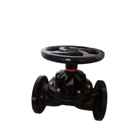
Cast Iron Diaphragm Valve
Price range: €35.20 through €388.47
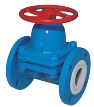
Ductile Iron Diaphragm Valve
Price range: €25.00 through €558.06