
Pressure Reducing Valve Manufacturer in Germany
Pressure reducing valves (PRVs) are used to maintain a controlled downstream pressure when the available supply pressure is higher than the pressure required by a process or piece of equipment. They automatically adjust the flow passage as demand changes, helping maintain a consistent outlet pressure across industrial piping and utility systems.
Our manufacturing range includes pressure reducing valves for steam, water, compressed air, nitrogen, industrial gases and compatible process fluids. These valves are used in power plants, chemical processing facilities, water distribution networks, industrial heating systems and general plant utilities.
Available configurations can be selected to suit the required inlet and outlet pressures, flow capacity, operating temperature and installation conditions.
Pressure Reducing Valve Types
Our range includes:
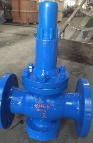
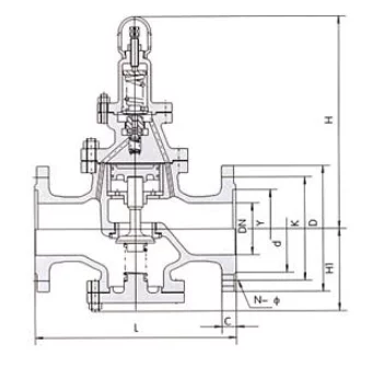
Direct Acting Pressure Reducing Valve
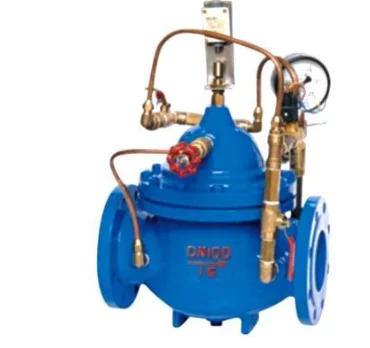
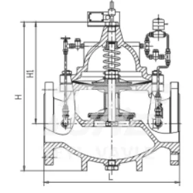
Pilot Operated Pressure Reducing Valve
Steam Pressure Reducing Valve
Water Pressure Reducing Valve
Gas Pressure Reducing Valve
Compressed Air Pressure Reducing Valve
High Pressure Reducing Valve
Pressure Reducing Valve Technical Specifications
|
Parameter |
Technical Specification |
|---|---|
|
Size Range |
DN15–DN300 |
|
Pressure Rating |
PN16, PN25, PN40 / ASME Class 150–600 |
|
Valve Design |
Direct acting or pilot operated |
|
Body Materials |
Cast iron, ductile iron, ASTM A216 WCB carbon steel, ASTM A351 CF8/CF8M stainless steel and bronze for selected designs |
|
Trim Materials |
Stainless steel, bronze or suitable corrosion-resistant alloys |
|
Diaphragm Materials |
NBR, EPDM or other service-compatible materials |
|
Seat and Seal Materials |
NBR, EPDM, FKM, PTFE or metal seating, depending on service |
|
End Connections |
Flanged, threaded or butt-weld, depending on valve design |
|
Pressure Adjustment |
Adjustable downstream pressure within the selected regulator’s spring or pilot range |
|
Controlled Media |
Steam, water, compressed air, nitrogen, compatible industrial gases and process fluids |
|
Flange Standards |
EN 1092-1, EN 1092-2 or ASME B16.5, as applicable |
|
Pressure Testing |
EN 12266-1 or applicable project requirements |
|
European Compliance |
PED 2014/68/EU, where applicable |
Specifications depend on the selected valve design and operating conditions. Available sizes, pressure ratings and material combinations should be confirmed for each application.
Downstream Pressure Regulation and Performance
A pressure reducing valve responds to changes in downstream pressure by adjusting the position of its regulating element. When system demand increases, the valve allows more flow. As demand decreases, it restricts the flow to maintain the selected outlet pressure.
The ability to maintain a consistent pressure depends on the valve’s regulating mechanism, available differential pressure and operating flow range.
Several performance characteristics should be considered during selection:
Downstream pressure adjustment range
Minimum and maximum flow capacity
Pressure droop or offset
Response to changing system demand
Minimum operating differential pressure
Shut-off performance
Pressure droop refers to the variation in regulated outlet pressure as flow demand changes. Its magnitude depends on the selected regulator and operating conditions.
For systems with considerable changes in flow demand, the valve must have sufficient capacity to maintain acceptable regulation at both minimum and maximum operating conditions.
Pressure Reducing Valve Sizing and Selection
Correct sizing is essential for reliable pressure regulation. Selecting a valve based only on pipeline diameter can lead to insufficient flow capacity, unstable pressure control or excessive noise.
The following operating data should be considered when selecting an industrial pressure reducing valve:
|
Selection Parameter |
Required Information |
|---|---|
|
Inlet Pressure |
Minimum, normal and maximum supply pressure |
|
Outlet Pressure |
Required downstream pressure and acceptable variation |
|
Flow Capacity |
Minimum, normal and maximum flow rates |
|
Process Medium |
Type of fluid and relevant physical properties |
|
Operating Temperature |
Minimum and maximum process temperature |
|
Flow Coefficient |
Required Kv or Cv |
|
Differential Pressure |
Available pressure drop across the regulator |
|
Turndown |
Required operating flow range |
|
Installation |
Pipe size, connection type and available space |
Applications involving substantial pressure reduction require additional consideration of flow velocity and fluid behavior.
For liquid service, cavitation can occur when local pressure falls below the fluid’s vapor pressure. In gas and steam applications, high pressure ratios may lead to choked flow and increased noise.
Where a single valve cannot accommodate the required pressure reduction or operating range, staged pressure reduction may be considered.
Pressure Reducing Valve Industries and Applications
Pressure reducing valves are installed in industrial systems where equipment or downstream piping requires a controlled supply pressure.
|
Industry |
Typical Applications |
|---|---|
|
Oil and Gas |
Utility gas regulation, compressed air supply and auxiliary process systems |
|
Petrochemical |
Steam distribution, nitrogen supply and process utility pressure control |
|
Power Generation |
Boiler auxiliary steam, plant utilities and water pressure regulation |
|
Chemical Processing |
Process water, compressed air, industrial gases and heating systems |
|
Water and Wastewater Treatment |
Distribution networks, pumping stations and pressure management |
|
HVAC and District Heating |
Heating water, steam supply and utility pressure regulation |
|
Marine and Shipbuilding |
Steam, compressed air, freshwater and marine utility systems |
|
Food and Pharmaceutical |
Utility steam, process water and compressed air systems |
|
General Manufacturing |
Equipment supply pressure, industrial heating and plant utility networks |
Pressure Reducing Valve Installation and Accessories
A pressure reducing valve should be installed in the specified flow direction, with sufficient access for adjustment, inspection and maintenance.
The piping arrangement may include upstream and downstream isolation valves, strainers, pressure gauges and associated pilot accessories. These components support routine monitoring and help protect the regulator from contaminants in the supply line.
Steam installations may require condensate separation and drainage, while water systems with significant pressure reduction should be assessed for cavitation and downstream piping conditions.
Where regulator failure could expose downstream equipment to excessive pressure, a separate overpressure protection arrangement may be necessary. A pressure reducing valve is intended for pressure regulation and should not be treated as a replacement for a suitably specified safety or relief device.
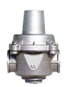
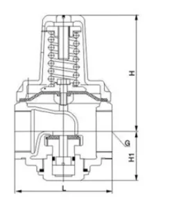
Direct Acting Pressure Reducing Valve
Price range: €1,030.00 through €2,087.00
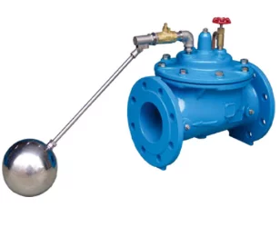
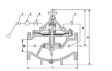
Float Control Valve
Price range: €301.00 through €1,933.00
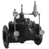
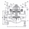
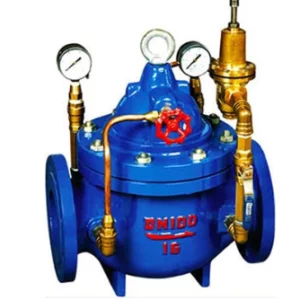
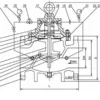
Pressure Reducing Valve
Price range: €238.32 through €334.29
Pressure Relief Valve
Price range: €347.00 through €2,101.00
Steam Pressure Reducing Valve
Price range: €260.60 through €674.90
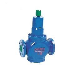
Water Pressure Reducing Valve
Price range: €348.00 through €1,767.00