
Check Valve Manufacturer in Germany
Check valves automatically prevent reverse flow in piping systems without requiring external actuation. The closure element responds to changes in flow direction and differential pressure, protecting pumps, compressors, process equipment and pipelines against backflow and associated pressure disturbances.
Automatic Prevention of Reverse Flow:
A check valve remains open while the differential pressure across the valve is sufficient to move the disc, plate or other closure element away from its seat.
When forward flow decreases, the opening force also reduces. If the flow stops or begins to reverse, gravity, spring force, backpressure or a combination of these forces moves the closure element toward the seat.
This automatic operating principle prevents reverse flow without a manual operator or actuator.
Check valves are commonly installed downstream of:
- Pumps
- Compressors
- Parallel equipment trains
- Storage and process systems
- Pressure control equipment
- Water distribution systems
Correct valve selection is important because poor closing behaviour can contribute to disc impact, vibration and hydraulic pressure surges.
Swing, Lift, Dual Plate and Non Slam Designs:
Different check valve designs provide different closing characteristics and pressure loss behaviour.
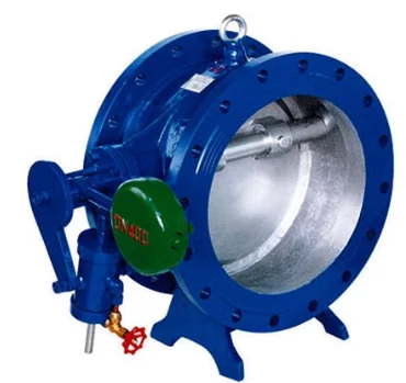
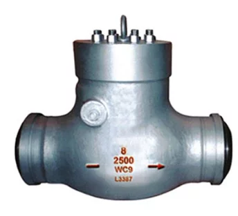
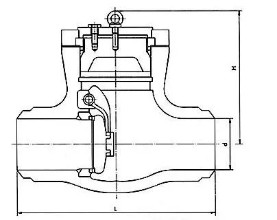
- Swing Check Valve: Hinged disc design for low resistance flow in larger pipelines.
- Lift Check Valve: Vertically moving disc suited to controlled closing and higher-pressure service.
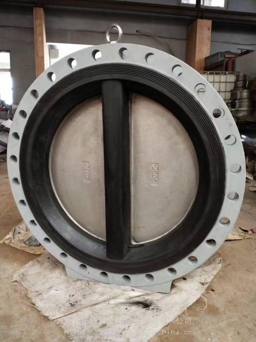
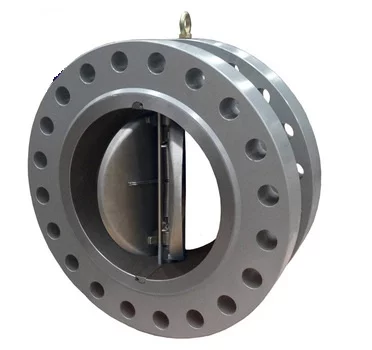
- Dual Plate Check Valve: Spring assisted twin plates provide fast closing and compact installation.
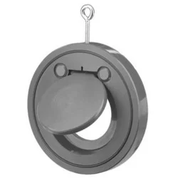
- Single Plate Wafer Check Valve: Lightweight wafer design with short face to face dimensions.
- Non-Slam Check Valve: Spring assisted closure reduces reverse velocity, impact and pressure surge.
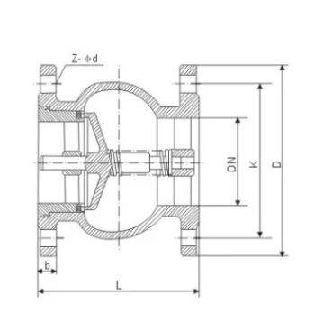
- Tilting Disc Check Valve: Offset pivot disc combines low flow resistance with faster closing response.
Cracking Pressure and Disc Movement:
Cracking pressure is the minimum differential pressure required to initiate movement of the closure element from its seat.
The required value depends on:
- Disc or plate weight
- Spring force
- Installation orientation
- Valve size
- Fluid density
- Seat configuration
- Internal geometry
For spring assisted check valves, cracking pressure can be selected according to the spring design.
Once the valve opens, disc position varies with flow velocity. Stable operation should keep the closure element sufficiently open without continuous movement or chatter.
At low or highly variable flow rates, an oversized check valve may operate with the disc only partially open. This can accelerate wear on hinges, shafts, springs and seating surfaces.
Reverse Velocity and Slam Prevention:
Check valve slam occurs when reverse flow develops before the closure element reaches the seat. The moving fluid column can then force the disc closed at high velocity, creating mechanical impact and a pressure transient.
Factors influencing slam include:
- Rate of flow deceleration
- Pump trip characteristics
- Pipeline length
- Fluid velocity
- Disc travel
- Disc inertia
- Spring force
- Valve installation position
Dual plate, spring assisted and non slam designs reduce closure travel and can respond more quickly when flow begins to decelerate.
Technical Specifications:
| Parameter | Typical Specification |
| Size Range | DN15–DN1200 |
| Pressure Rating | PN10–PN450 / ASME Class 150–2500 |
| Types | Swing, Lift, Dual Plate, Single Plate Wafer, Tilting Disc, Non Slam |
| Body Materials | Carbon Steel, Stainless Steel, Ductile Iron, Forged Steel, Bronze, Duplex, Super Duplex and Special Alloys |
| Trim Materials | Stainless Steel, hard faced alloys, Monel or Hastelloy where required |
| Seating | Metal Seat, EPDM, NBR, PTFE/RPTFE or other service-compatible seats |
| End Connections | Flanged, Wafer, Lug, Butt Weld, Threaded |
| Design Standards | API 594, EN 12334, ASME B16.34, API 6D where applicable |
| Face to Face | ASME B16.10 / API 594 / EN requirements according to design |
| Testing | API 598, EN 12266-1, ISO 5208 where applicable |
| Operation | Self Actuated |
Either use one in category and the other in product , cannot indicate material twice in just category
Disc and hinge components commonly use stainless steel or body compatible alloy materials.
Installation Orientation and Selection:
Check valve orientation depends on the valve design.
Swing check valves are generally installed in horizontal lines or vertical pipelines with upward flow when the specific design permits it. Lift and spring assisted designs may support other installation orientations, subject to manufacturer requirements.
Selection should consider:
- Flow direction
- Minimum and maximum flow rate
- Fluid velocity
- Pressure rating
- Operating temperature
- Installation orientation
- Required cracking pressure
- Allowable pressure drop
- Pump shutdown characteristics
- Water hammer risk
Pump and Pipeline Applications:
Check valves are installed throughout industrial piping systems where reverse flow could damage equipment or interrupt process operation.
Typical applications include:
- Pump discharge lines
- Water transmission pipelines
- Cooling water systems
- Oil and gas pipelines
- Compressor discharge systems
- Steam and condensate systems
- Power generation facilities
- Chemical processing plants
- Marine and offshore piping
- Desalination systems
- Firewater networks
- Industrial utility systems
The appropriate check valve should be selected according to flow behaviour and closing dynamics rather than pressure class alone, particularly in large pumping and long pipeline systems where reverse velocity can generate significant surge pressure.
Dual Plate Lug Check Valve
Price range: €831.50 through €9,365.00
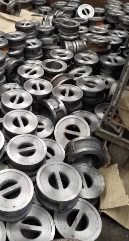
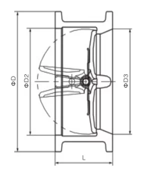
Dual Plate Wafer Check Valve
Price range: €12.21 through €14,544.35
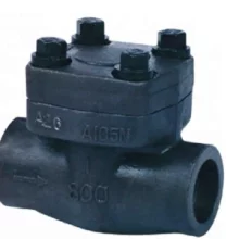
Forged Steel Swing Check Valve
Price range: €20.36 through €465.46
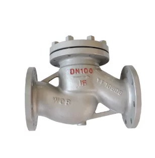
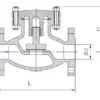
Lift Check Valve
Price range: €128.00 through €6,890.00
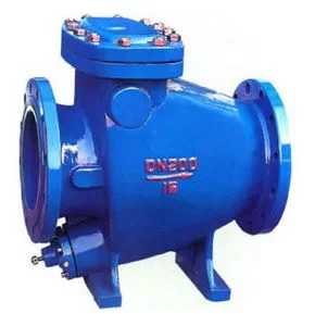
Non Slam Swing Check Valve
Price range: €232.00 through €477.00
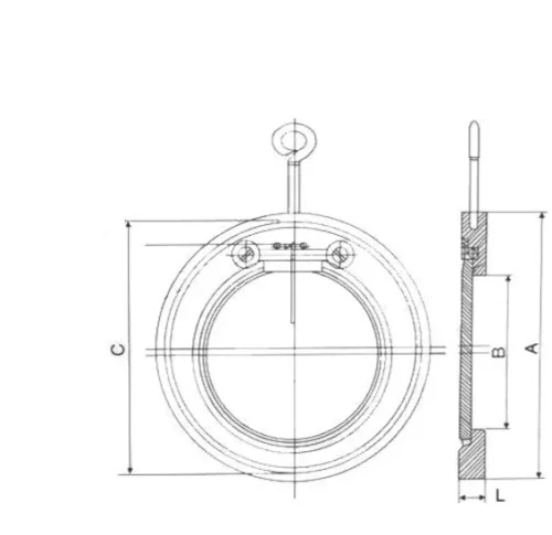
Single Plate Wafer Check Valve
Price range: €83.20 through €1,316.80
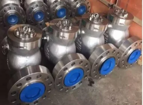
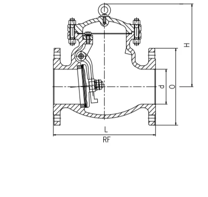
Swing Check Valve
Price range: €15.00 through €9,752.97