
Safety Valve Manufacturer in Germany
Excess pressure buildup in industrial systems can lead to equipment failure, process shutdowns, and serious safety risks. Safety valves are critical components that automatically release pressure once predefined limits are exceeded, ensuring system protection and operational continuity.
ValvesOnly Europe manufactures safety valves engineered for rapid response and reliable pressure relief under demanding conditions. As a Safety Valve Manufacturer in Germany, the valves are designed to meet EN and API standards with focus on accuracy, repeatability, and long-term performance.
Working Principle of Safety Valve
Safety valves operate by opening automatically when system pressure exceeds a set limit. Once the pressure returns to a safe level, the valve closes to prevent unnecessary loss of fluid.
This rapid opening and reseating action ensures protection against overpressure conditions without requiring external control.
Advantages of Safety Valves in Industrial Applications
- Protects systems from overpressure and equipment damage
- Automatic operation without external intervention
- Fast response to sudden pressure increases
- Ensures compliance with safety regulations
- Improves overall system reliability and safety
Types of Safety Valves Offered
Safety valve selection depends on pressure conditions, media type, and application requirements.
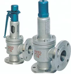
- Steam Safety Valve – Designed for high-temperature steam systems with precise pressure release
- Pressure Safety Valve – Used in gas and liquid systems for controlled pressure relief
- Thermal Safety Valve – Protects systems from pressure buildup due to temperature expansion
Safety Valve Design Standards (EN / API)
- EN ISO 4126 – Safety valve design standard
- API 526 – Flanged steel safety valves
- API 527 – Seat tightness of pressure relief valves
- DIN standards for industrial valve construction
Inspection and Testing Standards for Safety Valves
- EN 12266 – Pressure testing
- API 527 – Leakage testing
- Functional testing for set pressure and reseating performance
Body and Trim Material Compatibility
Material selection depends on pressure intensity, temperature conditions, and media characteristics, particularly in high-temperature and safety-critical applications.
| Material | European Grade | Typical Applications |
|---|---|---|
| Inconel | EN 2.4816 / 2.4856 | High-temperature and pressure relief systems |
| Carbon Steel | EN 1.0619 / 1.0618 | General pressure systems and industrial pipelines |
| Stainless Steel | EN 1.4408 / 1.4404 | Chemical processing and moderate corrosive environments |
| Incoloy | EN 1.4876 / 2.4858 | Elevated temperature systems and heat applications |
| Duplex Stainless Steel | EN 1.4462 | Offshore and corrosive service conditions |
| Super Duplex Stainless Steel | EN 1.4410 | Aggressive media with high chloride content |
| Hastelloy | EN 2.4819 / 2.4602 | Severe corrosion and chemical resistance applications |
| Alloy 20 | EN 2.4660 | Acidic environments and chemical handling |
| Titanium | EN 3.7035 / 3.7165 | Seawater and highly corrosive service conditions |
Industrial Applications of Safety Valves
- Oil and Gas Processing – Overpressure protection in pipelines and vessels
- Power Generation – Steam system safety and pressure control
- Petrochemical Plants – Protection in high-pressure processing units
- Water and Wastewater – Pressure relief in distribution systems
- Chemical Processing – Handling reactive and pressurized media
- Marine and Offshore – Safety protection in fluid systems
Special Features and Customization Options
- Accurate set pressure calibration for safety compliance
- Rapid opening and reseating mechanism
- Configurations for steam, gas, and liquid service
- Custom end connections for system compatibility
- Designs suitable for high-temperature applications
Pressure relief performance depends on correct valve selection based on system pressure limits, temperature conditions, and process requirements.
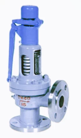
Full Lift Pressure Safety Valve
Price range: €260.00 through €6,667.00
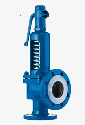
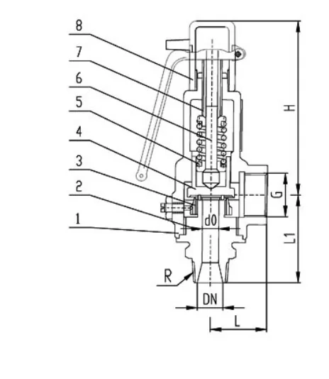
Full Lift Safety Valve
Price range: €260.00 through €6,667.00
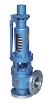
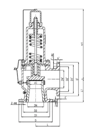
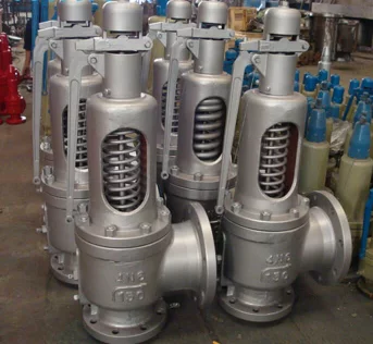
Low Lift Pressure Safety Valve
Price range: €213.00 through €6,442.00
Low Lift Safety Valve
Price range: €213.00 through €6,442.00
Steam Safety Valve
Price range: €260.00 through €6,667.00