
Control Valve Manufacturer in Germany
Control valves are designed for precise regulation of flow, pressure, temperature and liquid level in industrial process systems. By adjusting the flow passage in response to a control signal, these valves maintain stable process conditions across varying operating loads.
Our manufacturing range includes industrial control valves with pneumatic and electric actuation for applications in power generation, oil and gas, petrochemical processing, water treatment and industrial utility systems. Available configurations can be selected according to operating conditions, flow capacity, body material, trim design and control requirements.
Control valves can be manufactured in carbon steel, stainless steel, alloy steel, duplex and super duplex materials for liquids, gases, steam and demanding process media.
Control Valve Technical Specifications
|
Parameter |
Typical Specification |
|---|---|
|
Size Range |
DN20–DN400 |
|
Pressure Rating |
ASME Class 150–2500 / PN16–PN100, where applicable |
|
Body Materials |
ASTM A216 WCB/WCC, A217 WC6/WC9, A352 LCB/LCC, A351 CF8/CF8M/CF3/CF3M, duplex and super duplex stainless steel |
|
Trim Materials |
SS304, SS316, SS316L, hardened stainless steel and Stellite-faced options |
|
End Connections |
Flanged, butt weld, socket weld and threaded, depending on valve design |
|
Actuation |
Pneumatic or electric |
|
Pneumatic Actuator |
Spring-return diaphragm, single-acting or double-acting piston |
|
Electric Actuator |
Modulating or on/off |
|
Control Signal |
4–20 mA electrical; 0.2–1.0 bar (3–15 psi) pneumatic, where applicable |
|
Pneumatic Supply |
Typically 2–6 bar, depending on actuator requirements |
|
Flow Characteristics |
Linear, equal percentage and quick opening |
|
Fail Action |
Fail-open, fail-closed or fail-in-place, depending on actuator configuration |
|
Stem Packing |
PTFE or graphite |
|
Accessories |
Digital positioner, solenoid valve, limit switches, air filter regulator and position transmitter |
|
Pressure Design |
ASME B16.34 / EN 12516, as applicable |
|
Flow Sizing |
IEC 60534-2-1, where applicable |
|
Inspection and Testing |
IEC 60534-4 / EN 12266-1, as applicable |
Specifications are indicative. The available combinations of size, materials, pressure rating and actuation depend on the selected valve design and project requirements.
Pneumatic and Electric Control Valve Configurations
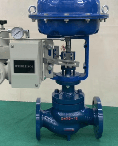
Industrial control valves are available with pneumatic or electric actuators for integration into automated process control systems. Actuator selection depends on the maximum differential pressure, required valve travel, control response, available utilities and process safety requirements.
Pneumatic control valves can be equipped with diaphragm or piston actuators, including spring-return and double-acting arrangements. Electro-pneumatic or digital positioners provide accurate valve positioning in response to the control signal.
Electric control valves use motor-driven actuators for automated valve positioning. Modulating configurations allow continuous adjustment of the valve opening, while on/off arrangements are available for applications requiring automated opening and closing.
Optional accessories include digital positioners, solenoid valves, limit switches, air filter regulators and position transmitters.
Fail-open, fail-closed or fail-in-place configurations can be selected according to the actuator design and required process safety function.
Control Valve Flow Characteristics and Trim Design
Control valve performance depends on the relationship between valve travel, flow capacity and operating differential pressure. The required flow characteristic and trim arrangement are selected according to the process conditions and control objectives.
Available flow characteristics include linear, equal percentage and quick opening, depending on valve construction.
Trim configurations may include contoured plugs, guided stems, cages, balanced plugs and multi-stage pressure-reduction arrangements.
For applications involving high differential pressure, cavitation, flashing or excessive noise, specialised trim designs can be considered to manage fluid velocity, pressure reduction and potential trim damage.
Appropriate trim selection helps maintain control performance while reducing erosion, vibration and premature wear under demanding operating conditions.
High-Pressure Control Valves for Industrial Applications
High-pressure control valves are used in process systems requiring accurate regulation under elevated operating pressures and significant differential pressure conditions.
Depending on the service, valve configurations may incorporate alloy steel or stainless steel construction, hardened trim surfaces, pressure-balanced designs and multi-stage pressure-reduction arrangements.
For high-pressure steam, gas and liquid applications, the valve must be selected according to the specified operating temperature, maximum differential pressure, required shut-off capability and flow conditions.
Actuator sizing must also account for the forces required to operate the valve throughout its specified operating range.
Control Valve Sizing and Selection
Correct control valve sizing is essential for achieving stable process regulation and reliable operation throughout the required operating range.
The main selection parameters include:
Minimum, normal and maximum flow rates
Inlet and outlet operating pressures
Required differential pressure
Fluid density, viscosity and operating temperature
Vapour pressure and cavitation potential
Required flow coefficient (Kv/Cv)
Rangeability and flow characteristics
Shut-off leakage classification
Actuator thrust or torque requirements
Noise and velocity limitations
Sizing calculations can be performed in accordance with the applicable IEC 60534 requirements. The selected valve and actuator arrangement must accommodate the specified process conditions and required control performance.
Control Valve Industries and Applications
Our industrial control valve range is intended for flow, pressure and temperature regulation across various industrial sectors.
|
Industry |
Applications |
|---|---|
|
Oil and Gas |
Gas pressure regulation, process flow control and pipeline pressure-reduction systems |
|
Petrochemical |
Reactor feed control, hydrocarbon processing and chemical circulation |
|
Power Generation |
Steam regulation, boiler feedwater control, condensate systems and cooling water |
|
Chemical Processing |
Chemical dosing, mixing, temperature regulation and process fluid control |
|
Water and Wastewater Treatment |
Pressure control, flow regulation and treatment process systems |
|
Marine and Shipbuilding |
Cooling circuits, utility systems and process fluid regulation |
|
HVAC and District Energy |
Chilled water regulation, heating water control and temperature management |
|
General Manufacturing |
Industrial utilities, automated production systems and process temperature control |
Each application requires an appropriate combination of body material, trim design, actuator configuration and operating characteristics.
Control Valve Manufacturing and Project Requirements
Industrial control valves can be configured according to the operating conditions, applicable design standards and project specifications.
Material selection, end connections, flow characteristics, actuator sizing and accessories are established according to the intended service and control requirements.
For project enquiries, relevant operating data should include the process medium, minimum and maximum flow rates, inlet and outlet pressures, operating temperature, required leakage classification and available actuator power or air supply.
These parameters support the selection of a suitable control valve configuration for the specified industrial application
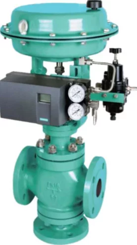
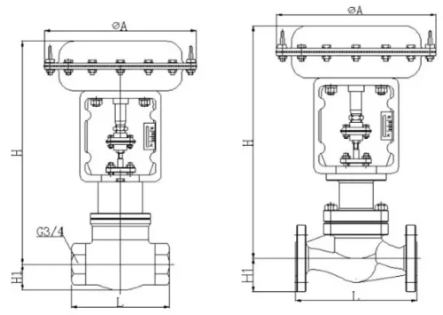
3 Way Converging and Diverging Control Valve
Price range: €1,054.00 through €9,664.00
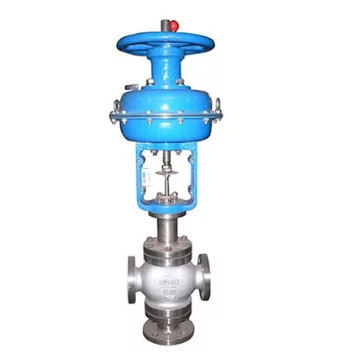

3 Way Pneumatic Diaphragm Control Valve
Price range: €1,539.00 through €9,754.00
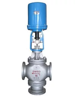
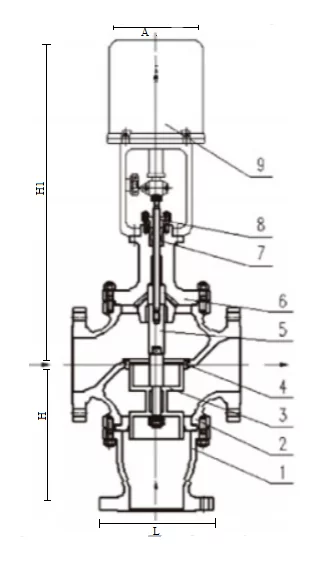
Electric 3 Way Control Valve
Price range: €2,138.00 through €9,954.00
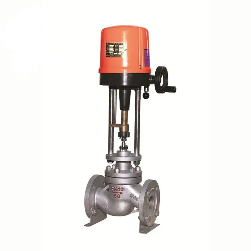
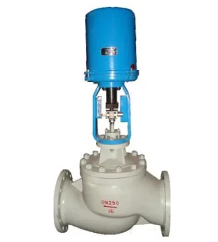
Electric Actuated Globe Control Valve
Price range: €939.50 through €3,743.00
Electric Cage Type Control Valve
Price range: €1,655.00 through €6,134.00
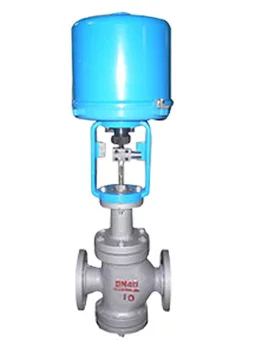
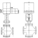
Electric Double Seat Control Valve
Price range: €1,365.00 through €5,834.00
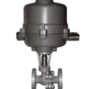
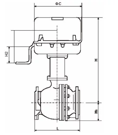
Electric O-type Shut-off Control Valve
Price range: €2,338.00 through €9,774.00
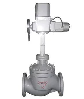
Electric Single Seat Control Valve
Price range: €1,265.00 through €5,734.00
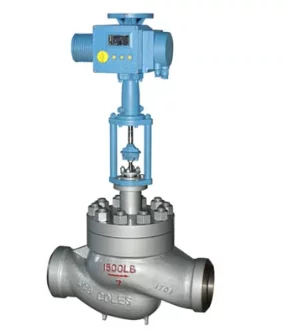
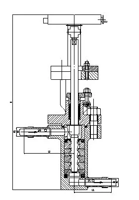
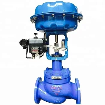
Pneumatic Actuated Globe type Control Valve
Price range: €882.60 through €3,643.00
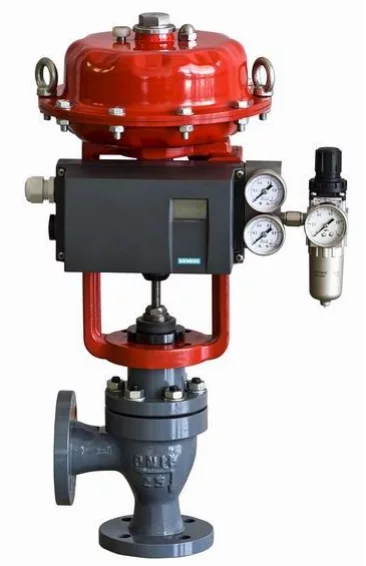
Pneumatic Angle Control Valve
Price range: €1,187.00 through €9,098.00
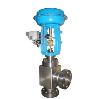
Pneumatic Angle Type High Pressure Regulating Control Valve
Price range: €1,187.00 through €9,098.00