
Check Valve Manufacturer in Germany
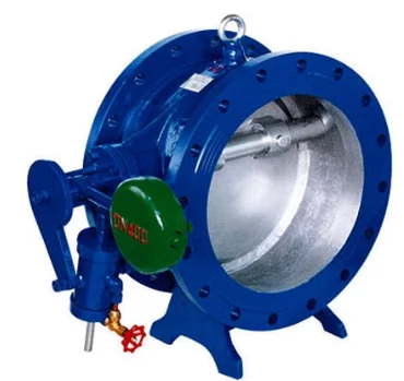
Check valves, also known as non-return valves (NRVs), prevent reverse flow in industrial piping systems. They operate automatically in response to flow direction and differential pressure, helping protect pumps, compressors, pipelines and connected equipment from backflow.
Our manufacturing range includes industrial check valves for water, steam, oil, gas, chemicals and other process fluids. Available configurations cover applications in power generation, petrochemical processing, water treatment, marine systems and industrial utilities.
Valve selection depends on the operating pressure, temperature, flow conditions, installation orientation and required closing performance. Different body designs, seating arrangements and end connections are available to suit specific project requirements.
Types of Check Valves
Our check valve range includes:
Swing Check Valve
Lift Check Valve
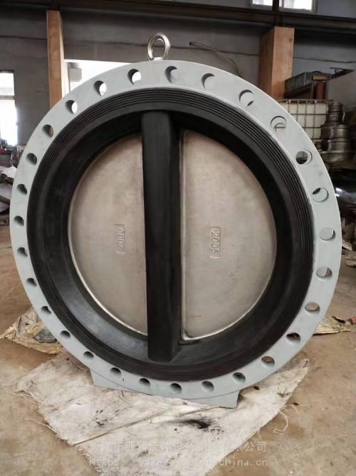
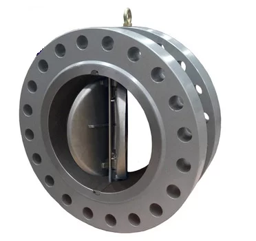
Dual Plate Check Valve
Single Plate Wafer Check Valve
Tilting Disc Check Valve
Non-Slam Check Valve
Axial Flow Check Valve
Piston Check Valve
Ball Check Valve
Check Valve Technical Specifications
|
Parameter |
Technical Specification |
|---|---|
|
Size Range |
DN15–DN1200 |
|
Pressure Rating |
PN10–PN450 / ASME Class 150–2500 |
|
Body Materials |
Cast iron, ductile iron, ASTM A216 WCB/WCC, ASTM A351 CF8/CF8M/CF3/CF3M, ASTM A105, ASTM A182 F304/F316, duplex, super duplex and special alloys |
|
Trim Materials |
Stainless steel, hard-faced alloys, Monel or Hastelloy, where required |
|
Seating |
Metal seated, EPDM, NBR, PTFE/RPTFE or other service-compatible materials |
|
End Connections |
Flanged, wafer, lug, butt-weld or threaded |
|
Operation |
Self-actuated by flow and differential pressure |
|
Design Standards |
API 594, EN 16767, ASME B16.34 or API 6D, as applicable |
|
Face-to-Face Dimensions |
ASME B16.10, API 594 or EN 558, according to design |
|
Pressure Testing |
API 598, EN 12266-1 or ISO 5208, as applicable |
|
European Compliance |
PED 2014/68/EU, where applicable |
Specifications vary according to valve type and construction. Available combinations of size, pressure rating, materials and end connections are subject to the selected design and project requirements.
Automatic Reverse Flow Prevention
A check valve opens when forward-flow differential pressure generates sufficient force to move the closure element away from its seat. As flow decreases, the opening force reduces, allowing the disc or plate to move toward the closed position.
Closure may be assisted by gravity, spring force or backpressure, depending on the valve construction. This automatic operation prevents reverse flow without the need for an external actuator or manual intervention.
Check valves are commonly installed on pump discharge lines, compressor outlets and process pipelines where changes in flow direction could affect equipment operation.
Correct valve selection is important for maintaining stable flow, limiting unnecessary pressure loss and avoiding excessive movement of internal components.
Cracking Pressure and Closing Performance
Cracking pressure is the differential pressure required to initiate opening of a check valve. It varies according to the closure element, spring arrangement, valve size and installation orientation.
During normal operation, the valve should open sufficiently to accommodate the required flow without continuous disc movement or chatter. An oversized check valve may remain partially open at low flow rates, causing vibration and accelerated wear.
Closing performance is particularly important in pumping systems where sudden changes in flow can create hydraulic pressure surges.
Check valve slam occurs when reverse flow develops before the closure element reaches its seat. The resulting impact can produce noise, vibration and pressure transients in the connected piping.
Spring-assisted and other fast-closing designs can help limit reverse-flow velocity, although their effectiveness depends on the system’s flow deceleration and operating conditions.
Check Valve Sizing and Selection
Check valves should be selected according to the actual operating conditions rather than pipeline size alone. Flow velocity, pressure drop and closing behaviour must be considered alongside the required pressure and temperature limits.
The main selection parameters include:
Minimum, normal and maximum flow rates
Operating pressure and temperature
Required cracking pressure
Fluid density and viscosity
Allowable pressure drop
Installation orientation and flow direction
Minimum flow velocity for stable operation
Pump shutdown or compressor trip conditions
Potential for water hammer or pressure surges
For pumping and long-distance pipeline applications, the closing characteristics should be evaluated against the expected rate of flow deceleration.
Where pressure transients are a concern, the selected valve should have appropriate closing dynamics for the operating system.
Check Valve Industries and Applications
Industrial check valves are installed wherever reverse flow could damage equipment, interrupt process operation or cause unwanted movement of fluids.
|
Industry |
Typical Applications |
|---|---|
|
Oil and Gas |
Pipeline backflow prevention, compressor discharge and process fluid systems |
|
Petrochemical |
Hydrocarbon processing, chemical transfer and utility pipelines |
|
Power Generation |
Boiler feedwater, condensate return, cooling water and steam systems |
|
Chemical Processing |
Process fluid circulation, chemical transfer and dosing systems |
|
Water and Wastewater Treatment |
Pump discharge, distribution networks and water transmission pipelines |
|
Marine and Offshore |
Seawater cooling, ballast water and marine utility systems |
|
Desalination |
Reverse osmosis systems, high-pressure pumping and water transfer |
|
Fire Protection |
Firewater pump discharge and fire protection piping |
|
General Manufacturing |
Compressed air, cooling circuits and industrial process utilities |
Check Valve Installation and Testing
Installation orientation must be compatible with the selected check valve design. Some configurations are intended primarily for horizontal pipelines, while others are suitable for vertical installation under specified flow conditions.
The valve should be installed in the correct flow direction, with sufficient upstream and downstream piping arrangements where required by the manufacturer.
Pressure and seat leakage testing should be carried out according to the applicable standard and project specifications. Additional inspection or testing may be required for critical process applications.
For project enquiries, the required information should include valve type, size, pressure rating, process medium, operating temperature, end connection, installation orientation and any specific closing or leakage requirements.
Dual Plate Lug Check Valve
Price range: €831.50 through €9,365.00
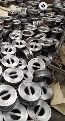
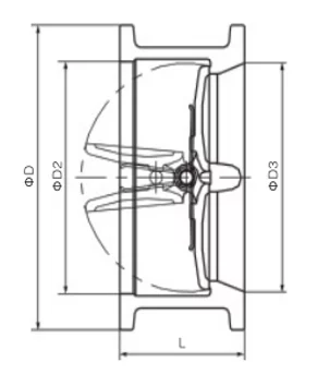
Dual Plate Wafer Check Valve
Price range: €12.21 through €14,544.35
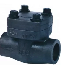
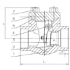
Forged Steel Swing Check Valve
Price range: €20.36 through €465.46
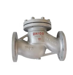
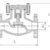
Lift Check Valve
Price range: €128.00 through €6,890.00
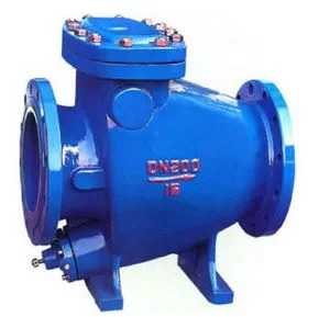
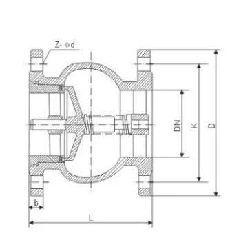
Non Slam Swing Check Valve
Price range: €232.00 through €477.00
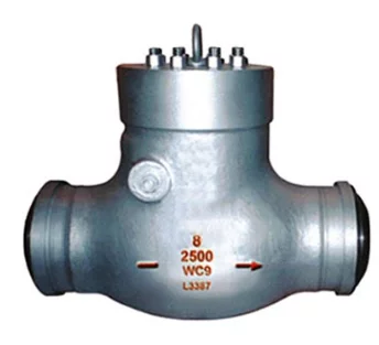
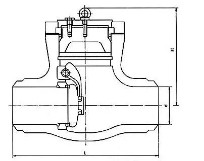
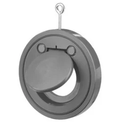
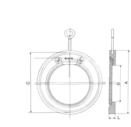
Single Plate Wafer Check Valve
Price range: €83.20 through €1,316.80
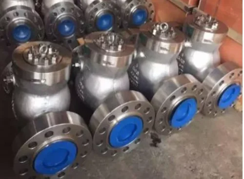
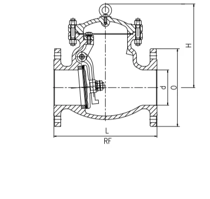
Swing Check Valve
Price range: €15.00 through €9,752.97