
Air Valve Manufacturer in Germany
Air valves manage accumulated air and vacuum conditions in pressurized water pipelines. They discharge large volumes of air while a system is filling, admit air when the pipeline is draining and, in combination designs, release smaller air pockets that collect while the line remains under pressure.
Air Management in Water Pipelines
Air can enter pipelines during filling, through pumps, through leaks under negative pressure or as dissolved air comes out of solution.
Uncontrolled air pockets can cause:
- Reduced pipeline capacity
- Increased pumping energy
- Flow instability
- Measurement errors
- Pressure transients
- Corrosion at air-water interfaces
Air valves are installed at selected pipeline locations to discharge or admit air according to changing system conditions.
Air Release, Air/Vacuum and Combination Designs
Air Release Valve
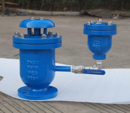
An automatic air-release valve removes relatively small volumes of accumulated air while the system remains pressurized.
Air/Vacuum Valve
An air/vacuum valve uses a large orifice to release bulk air during pipeline filling and admit large volumes of air during draining or negative-pressure conditions.
Combination Air Valve
A combination valve incorporates both large-orifice air/vacuum operation and small-orifice automatic air release.
This allows one valve to manage:
- Pipeline filling
- Normal pressurized operation
- Pipeline draining
Large Orifice and Small Orifice Operation
- During pipeline filling, large quantities of air must leave the system without generating excessive backpressure. The large orifice remains open until rising water lifts the float and closes it.
- During normal pressurized operation, accumulated air collects inside the valve body. A smaller automatic air release mechanism allows this air to escape without releasing significant quantities of water.
- During draining or a negative pressure event, the large orifice opens and admits atmospheric air into the pipeline.
- Correct coordination of these functions is important for pipeline surge and vacuum protection.
Technical Specifications
| Parameter | Typical Specification |
| Size Range | DN25–DN300 |
| Pressure Rating | PN10, PN16, PN25, PN40 |
| Types | Single Orifice, Double Orifice, Air/Vacuum, Kinetic, Combination |
| Body Materials | Ductile Iron, Cast Iron, Stainless Steel, Carbon Steel |
| Internal Trim | Stainless Steel |
| Float | Stainless Steel or engineered polymer depending on design |
| Seat / Seal | EPDM, NBR, FKM |
| End Connections | Flanged, Threaded |
| Operating Temperature | Approximately -10°C to +80°C in standard water-service configurations |
| Coating | Fusion-Bonded Epoxy where specified |
| Applicable Standards | EN 1074-4 / AWWA C512 |
| Pressure Testing | EN 12266-1 or applicable project requirement |
| Flanges | EN 1092-2 where applicable |
Air Valve Sizing Requirements
Air valve size should not be selected from pipeline diameter alone.
Required data includes:
- Pipeline diameter
- Filling rate
- Draining rate
- Maximum allowable differential pressure
- Pipeline length
- Elevation profile
- Pump flow rate
- Expected vacuum condition
- Surge-analysis results
Large orifice sizing determines how quickly air can leave or enter the pipeline.
Small orifice sizing is based on the volume of accumulated air that must be released while the pipeline is under pressure.
Pipeline Positioning and Installation
Air valves are commonly installed at:
- Pipeline high points
- Major changes in gradient
- Long rising sections
- Downstream of pumps where air accumulation is expected
- Upstream or downstream of control-valve locations according to hydraulic design
An isolation valve should normally be installed beneath the air valve so that maintenance can be performed without draining the entire pipeline.
The valve should be installed vertically unless the specific design permits another orientation.
Discharge outlets should also be positioned to prevent released water or contaminated fluid from creating a safety hazard.
Water Transmission and Pumping Applications
Typical applications include:
- Drinking-water transmission
- Distribution networks
- Pumping stations
- Sewage pipelines
- Effluent systems
- Desalination plants
- Irrigation networks
- Raw-water mains
- Firewater networks
- Industrial water systems
Correct air management improves hydraulic capacity and reduces the risk of vacuum conditions, but air valves should be selected as part of the complete pipeline surge and hydraulic design.
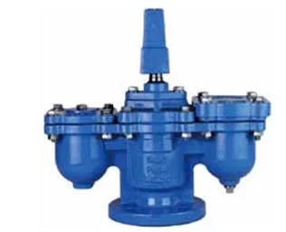
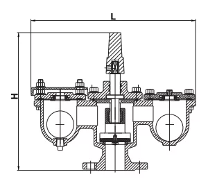
Double Orifice Air Valve
Price range: €56.00 through €779.00
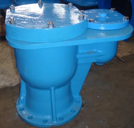
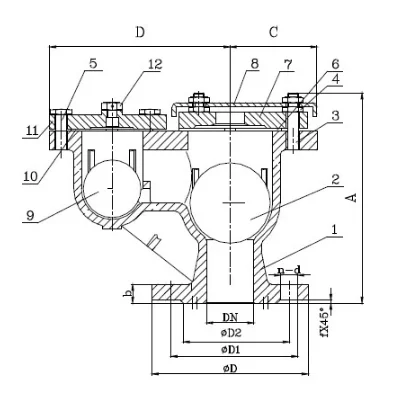
Double Orifice Kinetic Air Valve
Price range: €61.17 through €809.97
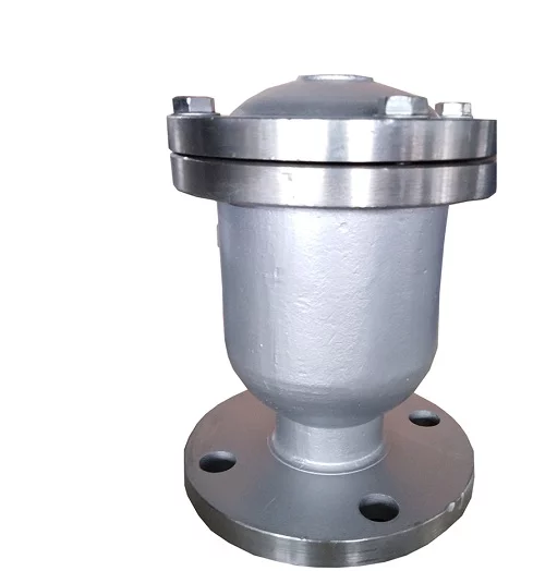
Single Orifice Air Valve
Price range: €44.72 through €65.68