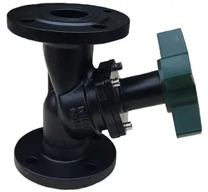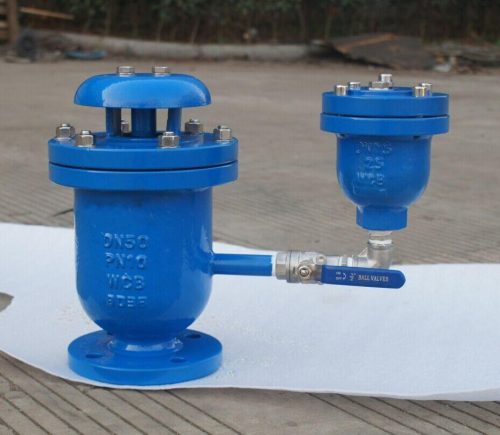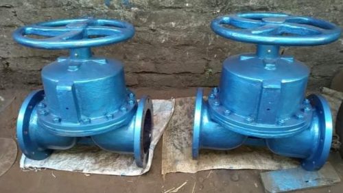

Balancing Valve Manufacturer in Europe
Balancing valves regulate and verify flow through individual branches of closed-loop piping systems so that each circuit receives the required design flow. By creating a measurable pressure differential across a calibrated flow path, the valve allows commissioning engineers to set and confirm water distribution without installing a separate permanent flow meter at every branch.
Flow Distribution Across Piping Circuits
Piping networks contain branches of different lengths, diameters and hydraulic resistance. Without balancing, circuits closest to the pump can receive excessive flow while hydraulically remote branches may receive less than the design requirement.
A balancing valve introduces a controlled resistance into each circuit so that the required flow can be established.
Correct hydraulic balancing can help provide:
- Design flow at terminal equipment
- Stable distribution between parallel circuits
- Controlled pump operating conditions
- Reduced unnecessary pumping energy
- Consistent heat-transfer performance
- More predictable system commissioning
The valve should be sized for the required flow rather than automatically matching the pipe diameter.
Static and Dynamic Balancing Methods
- Static Balancing Valve: Manually adjusted using differential-pressure readings and Kv data; the final setting can be locked with a memory stop.
- Dynamic Balancing Valve: Automatically adjusts to pressure or flow changes to maintain the required hydraulic condition within its operating range.
Flow Measurement and Presetting Mechanism
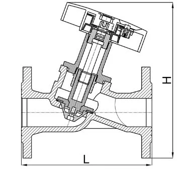
Manual balancing valves commonly incorporate two pressure test points positioned across the internal regulating element.
The commissioning process generally involves:
- Measuring differential pressure across the valve.
- Identifying the current valve opening.
- Using the valve-specific Kv chart.
- Calculating or reading the corresponding flow.
- Adjusting the handwheel until the design flow is reached.
- Locking or recording the final position.
Some designs incorporate a digital position indicator or numbered handwheel scale to improve repeatability.
A preset mechanism prevents the valve from being opened beyond the commissioned setting while still allowing it to be closed for maintenance.
Technical Specifications
| Parameter | Typical Specification |
| Size Range | DN15–DN600 |
| Pressure Rating | PN10–PN40; higher/class-rated designs according to valve construction |
| Body Materials | Ductile Iron, Carbon Steel, Stainless Steel, Bronze |
| Trim | Stainless Steel, Bronze or service-specific material |
| Seals | EPDM, NBR, FKM, PTFE |
| Flow Setting | Manual Presetting / Dynamic Regulation where applicable |
| Measurement | Differential-Pressure Test Points |
| Flow Coefficient | Kv/Cv according to valve size and setting |
| End Connections | Flanged, Threaded, Welded or Grooved depending on design |
| Operation | Handwheel; automated options for selected designs |
| Flanges | EN 1092 / ASME B16.5 where applicable |
| Testing | EN 12266-1 or applicable product requirement |
| European Compliance | PED 2014/68/EU where applicable |
Test Ports and Differential Pressure Measurement
Test ports provide measurement points upstream and downstream of the regulating element.
A portable differential-pressure instrument can be connected to these ports to determine pressure drop through the valve.
Flow is related to pressure differential through the valve flow coefficient. For water service, the measured differential pressure and the valve-specific Kv value can be used to determine approximate flow.
Test points should remain:
- Accessible
- Free from blockage
- Properly sealed
- Protected during normal operation
The manufacturer’s flow chart should always correspond to the exact valve size and preset position.
Installation and Commissioning Requirements
Balancing valves should be installed according to the marked direction of flow and with sufficient space for measurement and adjustment.
Important requirements include:
- Flush the pipeline before commissioning.
- Install the valve in the specified flow direction.
- Provide adequate access to test points.
- Support piping independently.
- Avoid severe flow disturbance immediately upstream where measurement accuracy is important.
- Measure system flow at normal operating condition.
- Record the commissioned setting.
- Lock or set the memory stop after adjustment.
After pump, control-valve or system modifications, hydraulic balance should be checked again.
Industrial Distribution-System Applications
Balancing valves are used in:
- District heating networks
- District cooling systems
- Chilled water circuits
- Heating water systems
- Cooling water loops
- Industrial process water systems
- Power plant auxiliary systems
- Marine cooling circuits
- Heat exchanger branches
- Pumped utility networks
Their primary function is not simply throttling but measurable and repeatable hydraulic adjustment so that the intended flow distribution is achieved throughout the piping system.