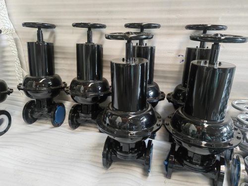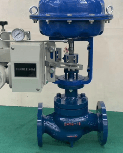

Plunger Valve Manufacturer in Germany
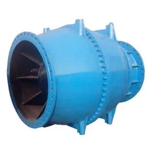
Plunger valves are control valves designed for regulating pressure and flow in water pipelines where substantial pressure differences or changing flow conditions must be managed. An axially moving plunger changes the annular flow area inside the valve, allowing controlled pressure reduction while maintaining a defined hydraulic flow path.
Pressure and Flow Control in Water Pipelines:
Plunger valves are intended for continuous regulating duty rather than simple open close isolation.
The valve can be used to:
- Reduce downstream pressure
- Regulate pipeline flow
- Control reservoir discharge
- Manage pump discharge conditions
- Maintain defined operating points
- Control flow entering treatment or distribution systems
Because the internal opening changes progressively with plunger travel, flow can be adjusted over a broad operating range.
Axial Plunger Movement and Annular Flow Path:
- The plunger moves in the same general direction as the pipeline axis.
- As it retracts, an annular opening develops around the plunger and allows water to pass through the valve. Moving the plunger toward the seat gradually reduces this flow area.
- This arrangement provides a controlled and symmetrical internal flow path.
- The axial movement allows the valve to regulate flow without placing a large disc directly across the pipeline. Depending on the valve configuration, the outlet geometry or control cylinder can also be designed to manage the location and intensity of pressure reduction.
Cavitation and Outlet Velocity Control:
Large pressure differences can cause local fluid pressure to fall below the vapour pressure of water. Vapour bubbles then form and collapse as pressure recovers, producing cavitation.
Severe cavitation can result in:
- Noise
- Vibration
- Pitting
- Surface erosion
- Damage to downstream piping
- Reduced valve life
Plunger valve selection should therefore consider both pressure ratio and flow velocity.
For demanding pressure reduction duties, suitable outlet control devices can divide or modify the flow path to move cavitation away from critical valve surfaces and improve energy dissipation.
Whether an anti cavitation arrangement is required should be determined from the actual hydraulic operating envelope.
Body and Plunger Construction:
Large water service plunger valves commonly use ductile iron body sections with stainless steel components in the internal flow and sealing areas.
Typical construction can include:
- Ductile iron front and rear body
- Stainless steel plunger or piston
- Stainless steel seat components
- Stainless steel shaft
- Bronze bushings
- NBR sealing elements
- PTFE bearing or bushing components where applicable
Internal materials are selected to provide resistance to corrosion, wear and repeated movement.
Protective coatings can be applied to ductile iron surfaces according to water service or project requirements.
Technical Specifications:
| Parameter | Typical Specification |
| Size Range | DN100–DN2000 |
| Pressure Ratings | PN10, PN16, PN25 |
| Body Material | Ductile Iron; Stainless Steel configurations where specified |
| Plunger / Piston | Stainless Steel |
| Seat | Stainless Steel |
| Shaft | Stainless Steel |
| Bushings | Bronze / PTFE according to component |
| Seals | NBR or service-compatible elastomer |
| End Connections | Flanged |
| Operating Temperature | Up to approximately 120°C depending on materials and configuration |
| Operation | Gear Operated, Electric Actuated, Pneumatic Actuated |
| Flange Connection | EN flange requirements according to pressure rating |
| Testing | EN 12266-1 or applicable project requirement |
Pressure Differential Selection:
A plunger valve should not be selected by nominal pipe diameter alone.
Required engineering data includes:
- Minimum flow rate
- Normal flow rate
- Maximum flow rate
- Maximum upstream pressure
- Required downstream pressure
- Static pressure conditions
- Pipeline diameter
- Water temperature
- Permissible velocity
- Cavitation limits
- Required operating time
The minimum, normal and maximum operating points should all be evaluated.
Water Transmission and Pumping Applications:
Plunger valves are mainly used in large water and hydraulic infrastructure.
Typical applications include:
- Drinking water transmission
- Pumping stations
- Water treatment plants
- Reservoir inlet and outlet lines
- Dam discharge systems
- Hydropower installations
- Irrigation networks
- Industrial cooling water systems
- Pressure management stations
- Large distribution networks
They can be installed downstream of pumps to regulate discharge or at strategic points in transmission systems where pressure and flow must be controlled over changing operating conditions.