
Safety Valve Manufacturer in Germany
Safety valves protect boilers, pressure vessels, pipelines and industrial equipment against excessive pressure. When system pressure reaches a predetermined set pressure, the valve opens automatically to release excess fluid. It closes once pressure falls to the specified reseating level.
Our manufacturing range includes industrial safety valves for steam, gas, vapour and liquid applications. Available configurations are suitable for power generation, oil and gas, petrochemical processing, industrial gas systems and general plant utilities.
Valve selection is based on the required relieving capacity, operating temperature, backpressure, process medium and applicable safety standards.
Types of Safety Valves
Our range includes conventional spring-loaded, balanced bellows, pilot-operated, full-lift, low-lift and steam safety valves.
Safety Valve Technical Specifications
|
Parameter |
Technical Specification |
|---|---|
|
Size Range |
DN15–DN300 inlet sizes, depending on design |
|
Pressure Rating |
PN10–PN450 / ASME Class 150–2500 |
|
Set Pressure |
Adjustable and calibrated within the selected spring or pilot range |
|
Cast Carbon Steel Body |
ASTM A216 WCB, WCC |
|
Forged Carbon Steel Body |
ASTM A105 |
|
Low-Temperature Steel Body |
ASTM A352 LCB, LCC / ASTM A350 LF2 |
|
Alloy Steel Body |
ASTM A217 WC6, WC9 |
|
Cast Stainless Steel Body |
ASTM A351 CF8, CF8M, CF3, CF3M |
|
Forged Stainless Steel Body |
ASTM A182 F304, F304L, F316, F316L |
|
Cast Iron / Ductile Iron Body |
ASTM A126 Class B / ASTM A536 65-45-12, for applicable designs |
|
Bronze Body |
ASTM B62 C83600, for selected applications |
|
Trim Materials |
ASTM A276 Type 410, 304, 316; Stellite-faced options |
|
Seat Design |
Metal seated or soft seated, depending on service |
|
End Connections |
Flanged or threaded, depending on valve design |
|
Service Media |
Steam, gas, vapour and compatible liquids |
|
Safety Valve Standards |
EN ISO 4126-1 / EN ISO 4126-4, as applicable |
|
API Standards |
API 520, API 526 and API 527, as applicable |
|
Equipment Codes |
ASME Section I / Section VIII, as applicable |
|
European Compliance |
PED 2014/68/EU, where applicable |
Specifications depend on the selected valve design and service conditions. Not all material, size and pressure-rating combinations are available for every model. Final pressure-temperature ratings, set-pressure limits and applicable certifications must be confirmed for the intended application.
Automatic Overpressure Protection
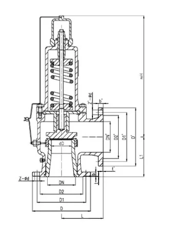
Safety valves operate independently of the normal process control system. In a direct spring-loaded design, a compressed spring holds the disc against the nozzle seat. As inlet pressure rises, the force acting on the disc increases until the valve reaches its specified opening condition.
The valve then releases the required amount of fluid to control the pressure increase. As system pressure falls to the reseating level, the closing mechanism returns the disc to its seat.
The opening response, discharge capacity and reseating characteristics depend on the valve construction and the requirements of the protected equipment.
Set Pressure, Relieving Performance and Sizing
Safety valve selection begins with the required relieving load. The valve must provide sufficient discharge capacity under the specified relief conditions while meeting the allowable pressure limits of the equipment.
The main pressure parameters include:
|
Parameter |
Description |
|---|---|
|
Set Pressure |
The specified pressure at which the valve begins to open under the applicable test conditions. |
|
Overpressure |
The pressure increase above the valve’s set pressure during relief. |
|
Accumulation |
The pressure increase above the maximum allowable working pressure of the protected equipment. |
|
Blowdown |
The difference between set pressure and reseating pressure. |
The following operating data is required for sizing and selection:
|
Sizing Parameter |
Required Information |
|---|---|
|
Relieving Capacity |
Required mass or volumetric flow rate |
|
Set Pressure |
Specified opening pressure |
|
Allowable Overpressure |
Permitted pressure increase during relief |
|
Relieving Temperature |
Temperature at the specified relief conditions |
|
Process Medium |
Steam, gas, vapour or liquid |
|
Fluid Properties |
Molecular weight, density, compressibility and other relevant properties |
|
Backpressure |
Superimposed and built-up backpressure, as applicable |
|
Discharge Coefficient |
Applicable certified or rated coefficient |
|
Orifice Area |
Required effective discharge area |
For gas and vapour service, sizing must account for compressible-flow behaviour. Liquid relief applications require appropriate fluid-property and backpressure calculations.
Where applicable, the calculated discharge area is used to select a standard API orifice designation. Final sizing and selection must comply with the governing equipment code and project requirements.
Safety Valve Industries and Applications
Industrial safety valves are installed wherever excessive pressure could damage equipment or compromise the integrity of a pressurised system.
|
Industry |
Typical Applications |
|---|---|
|
Oil and Gas |
Pressure vessels, separators, compressors and process systems |
|
Petrochemical |
Reactors, heat exchangers and hydrocarbon processing equipment |
|
Power Generation |
Steam boilers, steam headers and auxiliary systems |
|
Chemical Processing |
Process vessels, reactors and chemical handling systems |
|
Industrial Gas |
Gas receivers, compressors and pressurised gas systems |
|
Marine and Offshore |
Boilers, pressure vessels and marine utility systems |
|
Food and Pharmaceutical |
Steam generators, process vessels and utility systems |
|
General Manufacturing |
Compressed air receivers, heating equipment and industrial pressure systems |
Safety Valve Installation and Testing
Safety valves must be installed according to the applicable equipment code, project specification and manufacturer’s requirements.
The inlet piping should provide an adequate flow path without excessive pressure loss. The discharge arrangement must account for backpressure, reaction forces and the safe release or disposal of the relieved medium.
Inspection and testing may include set-pressure verification, seat leakage testing, visual and dimensional inspection, material certificate review, and nameplate verification. Capacity certification or additional performance testing may be required by the governing code.
Testing requirements and acceptance criteria are established according to the applicable safety standard and project specifications.
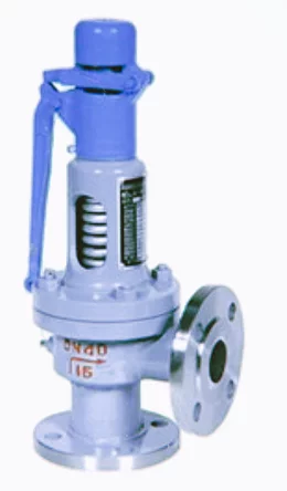
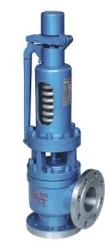
Full Lift Pressure Safety Valve
Price range: €260.00 through €6,667.00
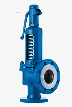
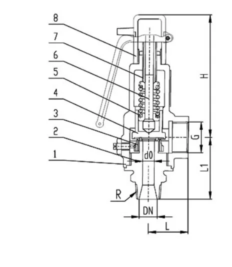
Full Lift Safety Valve
Price range: €260.00 through €6,667.00
Low Lift Pressure Safety Valve
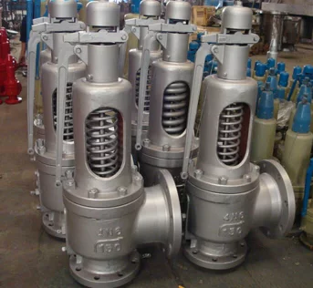
Price range: €213.00 through €6,442.00
Low Lift Safety Valve
Price range: €213.00 through €6,442.00
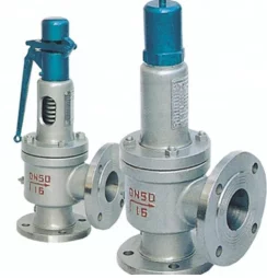
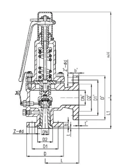
Steam Safety Valve
Price range: €260.00 through €6,667.00