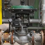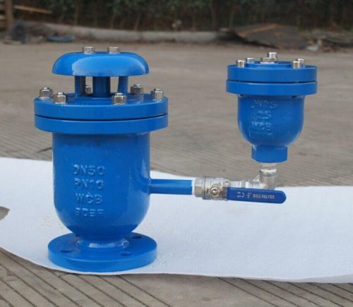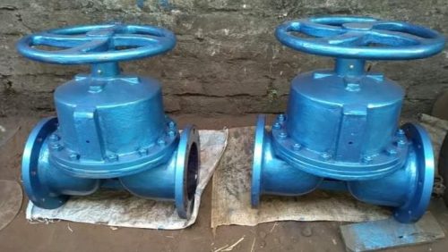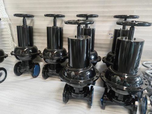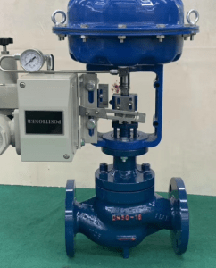
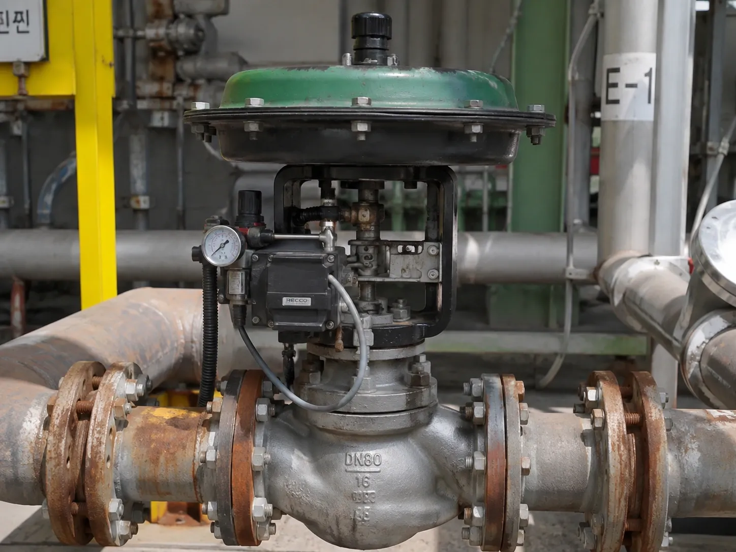
Pneumatic actuated valves have been central to the development of today’s process plants, where fluid and gas flow needs to be controlled precisely and repeatedly over vast piping networks and many control loops within various interrelated unit processes. The core of such a control system is represented by the Pneumatic actuated valve, which is a device that uses compressed air energy to perform the task of opening, closing or throttling a valve mechanically.
What is a Pneumatic Actuated Valve?
Pneumatically operated valve is made up of a standard process valve ball, butterfly, globe, diaphragm, or plug valve coupled with a pneumatically operated actuator which provides the necessary power to operate the valve’s closing element. Pressure from the instrument air is used to operate the piston or diaphragm, thereby providing linear or rotational movement of the valve’s stem or shaft.
This lets the valve integrate with a DCS, PLC, or SCADA system, so its position can be automatically regulated based on flow, pressure, temperature, and level loops.
Types of Pneumatic Actuated Valves:
- Pneumatic actuated ball valve
- Pneumatic actuated gate valve
- Pneumatic actuated globe valve
- Pneumatic actuated plug valve
- Pneumatic actuated knife gate valve
- Pneumatic actuated butterfly valve
How Pneumatic Valve Actuation Works?
The working principle is straightforward, but each step matters for reliable control:
- Signal input – A control signal, typically 4-20 mA or a digital fieldbus signal, reaches a valve positioner or solenoid valve.
- Air modulation – The positioner modulates instrument air pressure delivered to the actuator.
- Conversion – The air pressure causes a piston or diaphragm to move in a cylinder actuator or a diaphragm actuator respectively.
- Transfers – This motion then transfers to either quarter turn rotation of the valve (ball and butterfly valves) or stroke of the valve (globe and diaphragm valves).
- Flow change – The valve closure element repositions, changing the flow path and process condition.
The speed and precision of this air-to-motion conversion is what allows pneumatic systems to respond within seconds to changing process demands, a critical trait for interlocks, emergency shutdowns, and tight control loops.
Core Components of a Pneumatic Valve Automation Package:
A complete pneumatic valve automation package generally includes:
| Component | Function |
| Actuator body | Pneumatic cylinder, piston, or diaphragm housing that generates output torque or thrust |
| Valve positioner | Translates the control signal into a proportional air output, enabling throttling control rather than simple on-off switching |
| Solenoid valve | Directs and switches air flow to the actuator for on-off applications |
| Air filter regulator | Conditions and regulates the compressed air supply feeding the actuator |
| Limit switch box | Provides position feedback (open/closed status) back to the control system |
| Volume booster / quick exhaust valve | Improves actuator stroking speed for faster response |
| Mounting kit / bracket | Couples the actuator to the valve per NAMUR or ISO 5211 standards |
Applications in Automated Process Plants:
Pneumatically operated valves are used in various sectors where flow adjustment is required by automation in any control or safety system:
- Chemical & petrochemical processing – controlling feed flow of reactants, solvent recovery circuits, and batch transfer process
- Oil and gas – isolation and throttling service on separator vessels, pipeline manifolds, and distillation columns
- Power generation – steam and condensate control, boiler feedwater regulation, and cooling water isolation
- Water and wastewater treatment – chemical dosing lines, filtration backwash sequencing, and effluent diversion
- Pulp, paper, and bulk material processing – slurry transport, digester control, and washing stages
- Metals and mining processing – leach circuit control and tailings management
Benefits of Pneumatic Actuation Over Manual Operation:
- Rapid response time compared with manual valve operation useful in interlocks and emergency shutdown scenarios
- Fail safe design options through spring-return actuators, allowing valves to move to a predetermined safe position on loss of signal or air supply
- Remote operability, removing the need for personnel to access valves in hazardous, elevated, or confined locations
- Compatibility with hazardous area classifications, since pneumatic systems avoid electrical ignition sources at the actuator itself
- Simplified integration with existing plant instrument air infrastructure, reducing the need for additional power wiring at each valve location
Technical Selection Criteria for Pneumatic Valve Automation:
Specifying the right pneumatic actuated valve for a process application requires evaluating several interdependent engineering factors:
- Torque or thrust requirement – calculated from valve size, differential pressure, and seat friction, with a safety margin applied
- Cv value and flow characteristics – determines throttling behavior and valve sizing for the intended flow range
- Fail safe position – whether the valve should fail open, fail closed, or fail in last position on loss of air or signal
- Stroke speed – dictated by process dynamics quick exhaust valves or volume boosters may be needed for ESD response times
- Instrument air quality and supply pressure – must meet actuator specifications for dryness, filtration, and pressure range
- Materials of construction – selected for compatibility with process media, temperature, and corrosion potential
- Hazardous area certification – required where the valve operates in classified zones (e.g., ATEX, IECEx)
- Control signal type – on off (solenoid driven) versus modulating (positioner-driven) service
Maintenance Considerations:
Pneumatic actuated valves require periodic attention to sustain accurate control performance over their service life:
- Inspecting air filter regulators for contamination or moisture buildup
- Checking diaphragm or piston seals for wear and air leakage
- Verifying positioner calibration against the control signal range
- Testing fail safe stroke time during scheduled shutdown windows
- Confirming limit switch and position feedback accuracy against actual valve position
- Lubricating actuator linkages and yoke assemblies per manufacturer intervals
Routine testing of fail safe response particularly for valves tied to safety instrumented systems helps confirm the actuator will perform as intended during an actual process upset, rather than only during commissioning.
Sourcing Pneumatic Valve Automation for Your Plant:
Pneumatically operated valves convert the signal from the control system into exact and consistent valve movement, enabling remote control of process plants through speed of response and fail safe behavior. Correct actuator sizing and fail safe configuration are critical to the performance of these valves in service. Manufacturers such as Valvesonly Europe offer engineered pneumatic valve automation packages to help match the right valve and actuator to specific process conditions.